
WINDBEAM
TECHNOLOGY OVERVIEW
Zephyr Energy Corporation’s patented Windbeam micro generator captures energy from airflow to recharge batteries and power electronic devices.
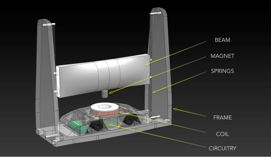
The Windbeam’s novel design allows it to operate silently in wind speeds as low as 2 mph. The generator consists of a lightweight beam suspended by durable long-lasting springs within an outer frame. The beam oscillates rapidly when exposed to airflow due to the effects of multiple fluid flow phenomena. A linear alternator assembly converts the oscillating beam motion into usable electrical energy. A lack of bearings and gears eliminates frictional inefficiencies and noise. The generator can operate in low-light environments unsuitable for solar panels (e.g. HVAC ducts) and is inexpensive due to low cost components and simple construction. The scalable technology can be optimized to satisfy the energy requirements and design constraints of a given application.
WINDBEAM
SCIENTIFIC PRINCIPLES APPLIED
Transverse Galloping
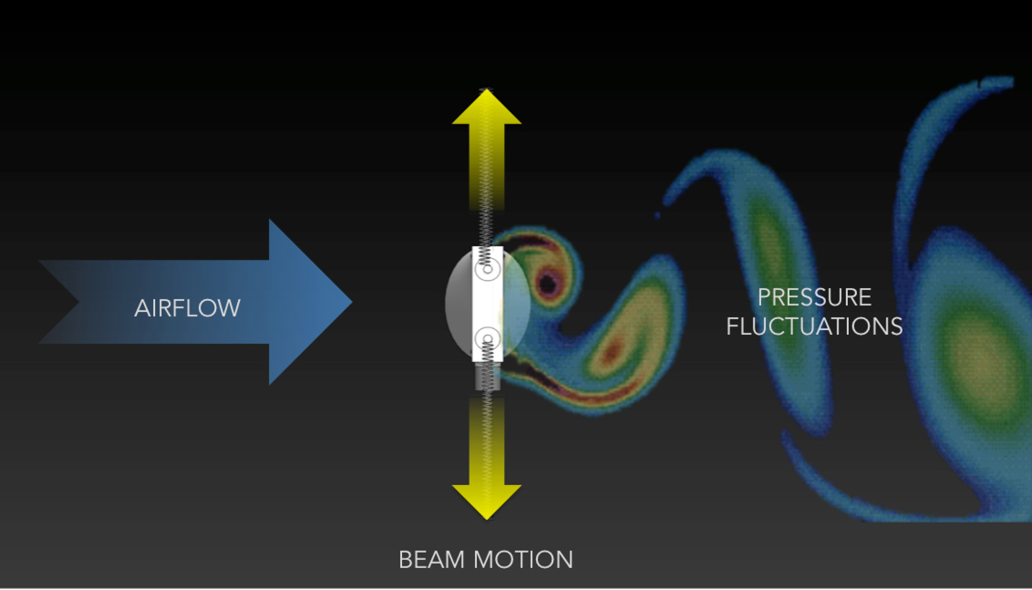
Occurring above a critical air velocity, transverse galloping is characterized by the progressively increasing amplitude of transverse vibration with increase of wind speed. Beams with non-circular cross sections are more susceptible to this type of oscillation. In general, when wind flow encounters a circular cylinder a force is exerted on this cylinder that is parallel to the direction as the wind. However, for a body with non-circular cross-section, there is an angle between the direction of wind flow and the force exerted on the beam.
As wind flows over the beam, a pressure differential is formed. The region just behind the beam is filled with turbulent eddies known to be around atmospheric pressure. The figure above shows streamlines flowing around the beam. The downward streamlines at the top of the beam indicate a high pressure pushing down on a lower pressure. Thus, the pressure at b must be lower than the pressure at a. Since a is far away from the disturbance, it can be considered to be at atmospheric pressure. Thus b is less than atmospheric pressure. Since the pressure at b is less than the pressure directly behind the beam, an upward lift force is induced in the beam.
This force will continue to push the beam upwards until the constraints of the system force the beam back downwards. In the case of the Windbeam, the constraints are found in the spring properties and dimensions of the frame. As the beam changes directions, the lower springs begin to pull downwards. Now, the same wind produces an opposite pressure differential that encourages the beam to move in a downward motion. This pattern continues and the system becomes what is known as a self-excited system.
The transverse galloping phenomenon has been observed in cold weather climates where ice builds up on transmission lines. The ice causes the cross-sectional shape of the line to become non-circular. Some of the various shapes induce large-amplitude oscillations in transmission lines in the direction perpendicular to the flow.
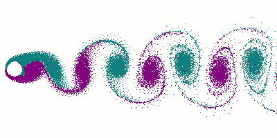
Vortex Shedding
Vortex shedding is another aerodynamic phenomenon contributing to the oscillations of the beam in a lower degree. It involves the formation of alternating vortices that form behind a bluff body (e.g. beam) when it is placed in fluid flow. An oscillating resultant lift force acts on the body as these vortices are shed. The intensity of these vortices and the resulting lift force are directly related to the cross-sectional shape and size of the bluff body. When the vortices are large enough, they create a low-pressure zone to which the beam would be drawn. The formation of vortices is shown below.